


Support both MOV & MOVX instruction. MOVX instruction is for GPIOA~GPIOF port. MOV instruction is for typical 8051 I/O. MCU provides 4 GPIO pins supporting 8051 Port 0 functions, can use MOV, SETB and CLR instruction to set the level status of GPIO. For more details please consult the GPIO Example Program.
Products
Applications
Supports
News & Events
ESG
Investors
About Us
Careers
subscribe newsletter
Back
Products
Power Management
Imaging Solutions
Motor Controllers and Drivers
Microcontrollers (MCUs)
Amplifiers
Interfaces
Back
Applications
Automotive
Consumer Electronics
Enterprise Systems
Industrial
Power Supplies
Back
Supports
Support Tools
Technical Information
- Overview
- WLINK Adapter Installation Guide
- ICE/ISP Operation Guide
- Evaluation Board User Guide
- Mass Production Programmer Operation Manual
- Mass Production Tools and Supplier Information
- ULINK ICE & ISP User Guide
- Peripheral Functions & Program User Guide
- Weltrend ARM 32-bit MCU Evaluation Boards List
Software Download
Reference Designs
Back
News & Events
News & Events
Back
ESG
Sustainable Development Policy and Implementation
Related Topics
Back
Investors
Financials
Corporate Governance
Shareholder Services
Contacts
Back
Careers

Q&A
Tools
Technical Specifications
Technical Specifications
Technical specifications related questions
01
Setting GPIO by MOV or MOVX instruction?
Ans.
02
How to reach the same effect with using external RESET pin for reset?
Ans.
Due to WT56F216/WT51F104 both build in LVD/LVDR, it can reach the effect by Low Voltage Detection Reset. For more details please consult the Low Voltage Detection Reset (LVDR) section in the Data Sheet.
03
How long does it take from MCU power-up to Reset completed? And how to solve the problem of peripheral LED blinking during this period?
Ans.
It takes 16ms from WT56F216/WT51F104 power-up to Reset completed.
The GPIO initial value of WT56F216/WT51F104 is Input Tri-state, and thus LED will not blink.
04
How to keep memory data for WT56F216/WT51F104 in power-down mode?
Ans.
Both WT56F216/WT51F104 support emulated E2PROM, and thus all status can be saved in flash after completing each power-on procedure. For more details please consult the Emulated E2PROM application documents.
05
How long does it take to program all over the flash for WT56F216 & WT51F104?
Ans.
WT56F216 programming 16Kbyte takes 20 seconds.
06
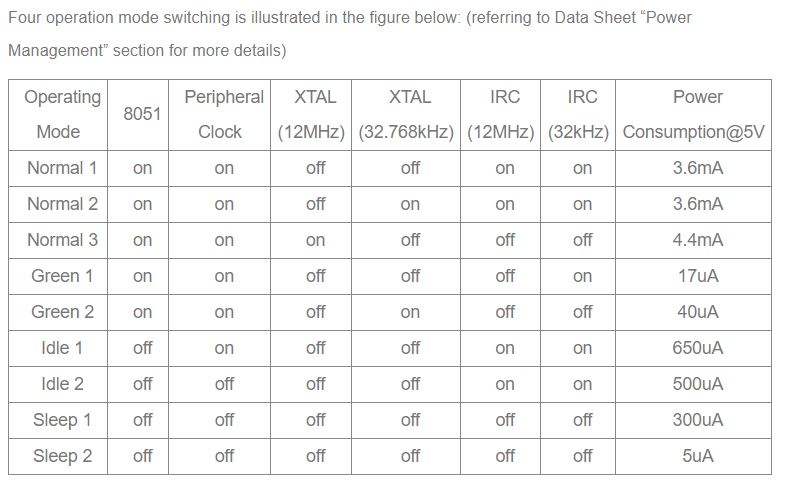
The power consumption of WT56F216/WT51F104 in each modes.
Ans.
07
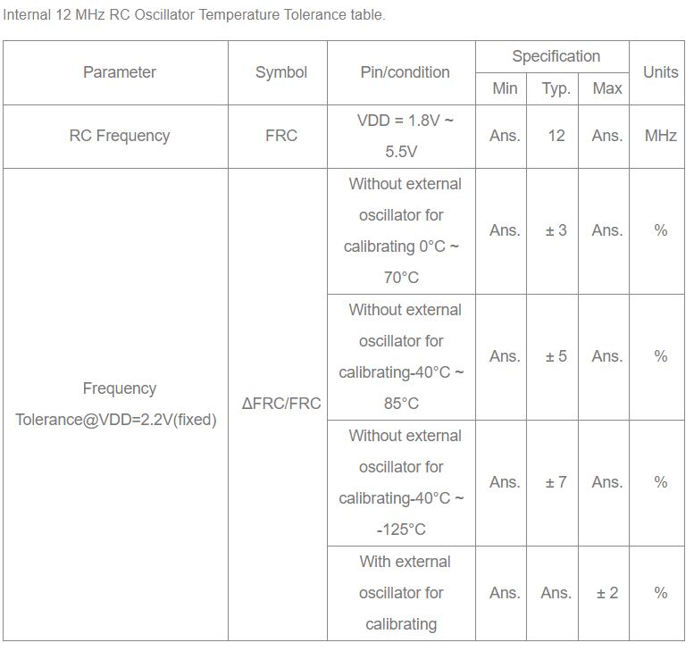
IRC 12MH Frequency Tolerance.
Ans.
08
Safety requlation testing for WT56F216 & WT51F104
Ans.
Tested by the qualified LAB, EFT can reach ±4KV; ESD Contact can reach ±4KV; Air can reach ±15KV.
09
Converting modes of ADC.
Ans.
1.Single Mode: turning on ADC & enabling Single conversion, then reading data after the conversion is completed.
2.Continuous Mode: turning on ADC & enabling continuous conversion, and MCU will keep on converting. After the convertion is completed, it will update A/D converter converting High/Low bytes Register.
3.Timer Auto Mode: working together with the time set by the Watch timer, Timer auto converting ADC data.
10
Is output phase of PWM adjustable?
Ans.
PWM Control Register provides output phase setting bit.
11
Does WT56F216/WT51F104 support external crystal oscillator 4 MHz or 8 MHz?
Ans.
It can support external crystal oscillator 4 MHz or 8 MHz but requiring enabling ISP_CHG_12M & UART_ISP_CHG bit in the program. IRC_12M_PD1 & IRC_12M_PD2 can be turned off only after the Source clock selecting external oscillator. For more details please consult the Power Management section and Example program in the Data Sheet.


